In precision oral care or grooming devices, system-level reliability is key. Yet, in recent OEM failure analysis cases, one hidden yet recurring issue is gaining attention: indicator failure triggered by motor resonance. While at first glance, a blinking light or non-responsive LED may seem like an isolated electrical problem, the root cause often lies in mechanical vibration patterns. How exactly does motor resonance affect indicator circuits, and what can manufacturers do to prevent this cascade failure?
Motor resonance occurs when a motor’s operational frequency aligns with the natural frequency of certain internal components—causing amplified vibrations. These can stem from:
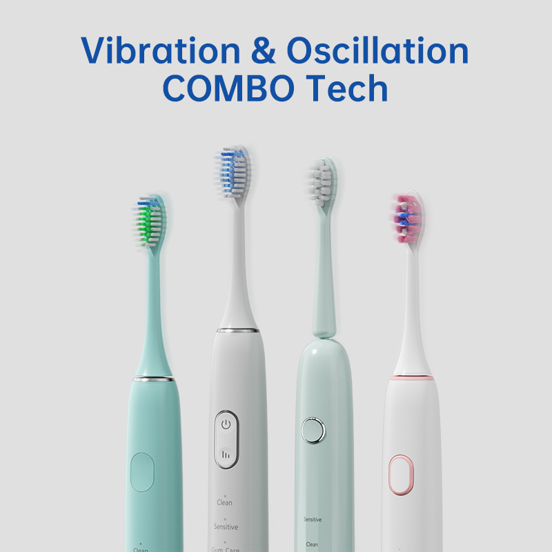
In devices like sonic toothbrushes or water flossers, this phenomenon isn’t just about sound or feel—it creates ripple effects across the electronic subsystems, including the indicator module.
Indicator failure can present in several forms:
Notably, these issues often appear only during active operation—which points toward vibration-induced instability rather than static electrical failure.
How exactly does motor resonance lead to indicator failure? Here’s the underlying mechanism:
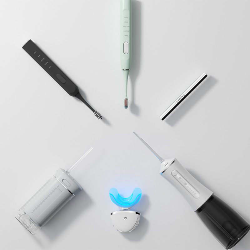
This interplay is particularly evident in compact, tightly packed devices where mechanical and electronic systems are in close proximity. Company web:https://www.powsmart.com/product/electric-toothbrush/
Preventing indicator failure due to motor resonance begins with mechanical-electrical co-design. Key strategies include:
Additionally, it’s critical to ensure motor vendors provide frequency stability reports across the operating voltage range.
Beyond design, production-stage and post-assembly QA processes can help catch resonance-linked issues before shipping:
These data-driven tests can be compiled into compliance reports for clients, especially in medical or high-end oral care markets.
By solving this invisible issue, manufacturers can:
For OEM clients, such reliability translates directly to higher customer satisfaction, fewer returns, and longer product lifecycle—which are strong commercial advantages in competitive markets.
Yes, motor resonance can indeed cause indicator failure—not through direct contact, but via vibration fatigue, noise interference, and mechanical-electrical misalignment. For B2B manufacturers, understanding and addressing this hidden failure pathway is essential for ensuring system-level quality. With proper vibration analysis, smart PCB layout, and QA testing protocols, manufacturers can deliver robust, stable products that reflect next-level engineering foresight. Contact us
.jpg)
.jpg)
.jpg)
Electric Toothbrush Manufacturing Company for OEM & ODM Projects
BPA Free Electric Toothbrush Bulk Supply | Health-Focused OEM Solutions
Parts Shortages and OEM Liability Disrupting Supply Chains?

What Are the Necessary Conditions for Professional Teeth Whitening Device Suppliers?
Manual vs. Electric Toothbrush Comparison: Which Wins for Clean Teeth?

How Does a Custom Brush Handle Mold Support a Calcified Deposit Remover Mechanism?
Whitening Device Customization Supplier
1-scaled.jpg)
How Can Brand Owners Partner with Reliable Teeth Whitening Device Factories to Create Differentiated Products?
Whitening Device Packaging Customization for OEM and ODM Brands
.jpg)
How does a rancher toothbrush Texas stand up to the lone star toothbrush challenge?
.jpg)
Taste Distortion Alongside pH Imbalance – Vicious Cycle?
Water Flosser Pressure Stability OEM | Consistent Performance Manufacturing
Do Multi-Color Toothbrushes in a Bundle Savings Deal Prevent Sibling Fights?
Texas Tax-Free Weekend Electric Toothbrush Wholesale Guide 2025
USB-C Water Flosser Wholesale | Fast-Charging Oral Irrigator Distributor
How Can Biomimetic Saliva Simulation Aid in the Health Technology Assessment of a New Mouthwash?

.jpg)
.jpg)
.jpg)
.jpg)
.jpg)

.jpg)